STP Topology Changes
In a stable Layer 2 topology, configuration BPDUs always flow from the root bridge toward the edge switches. However, changes in the topology (for example, switch failure, link failure, or links becoming active) have an impact on all the switches in the Layer 2 topology.
The switch that detects a link status change sends a topology change notification (TCN) BPDU toward the root bridge, out its RP. If an upstream switch receives the TCN, it sends out an acknowledgment and forwards the TCN out its RP to the root bridge.
Upon receipt of the TCN, the root bridge creates a new configuration BPDU with the Topology Change flag set, and it is then flooded to all the switches. When a switch receives a configuration BPDU with the Topology Change flag set, all switches change their MAC address timer to the forwarding delay timer (with a default of 15 seconds). This flushes out MAC addresses for devices that have not communicated in that 15-second window but maintains MAC addresses for devices that are actively communicating.
Flushing the MAC address table prevents a switch from sending traffic to a host that is no longer reachable by that port. However, a side effect of flushing the MAC address table is that it temporarily increases the unknown unicast flooding while it is rebuilt. Remember that this can impact hosts because of their CSMA/CD behavior. The MAC address timer is then reset to normal (300 seconds by default) after the second configuration BPDU is received.
TCNs are generated on a VLAN basis, so the impact of TCNs directly correlates to the number of hosts in a VLAN. As the number of hosts increases, the more likely TCN generation is to occur and the more hosts that are impacted by the broadcasts. Topology changes should be checked as part of the troubleshooting process. Chapter 3 describes mechanisms such as portfast that modify this behavior and reduce the generation of TCNs.
Topology changes are seen with the command show spanning-tree [vlan vlan-id] detail on a switch bridge. The output of this command shows the topology change count and time since the last change has occurred. A sudden or continuous increase in TCNs indicates a potential problem and should be investigated further for flapping ports or events on a connected switch.
Example 2-7 displays the output of the show spanning-tree vlan 10 detail command. Notice that it includes the time since the last TCN was detected and the interface from which the TCN originated.
Example 2-7 Viewing a Detailed Version of Spanning Tree State
SW1# show spanning-tree vlan 10 detail
VLAN0010 is executing the rstp compatible Spanning Tree protocol
Bridge Identifier has priority 32768, sysid 10, address 0062.ec9d.c500
Configured hello time 2, max age 20, forward delay 15, transmit hold-count 6
We are the root of the spanning tree
Topology change flag not set, detected flag not set
Number of topology changes 42 last change occurred 01:02:09 ago
        from GigabitEthernet1/0/2
Times:  hold 1, topology change 35, notification 2
        hello 2, max age 20, forward delay 15
Timers: hello 0, topology change 0, notification 0, aging 30
The process of determining why TCNs are occurring involves checking a port to see whether it is connected to a host or to another switch. If it is connected to another switch, you need to connect to that switch and repeat the process of examining the STP details. You might need to examine CDP tables or your network documentation. You can execute the show spanning-tree [vlan vlan-id] detail command again to find the last switch in the topology to identify the problematic port.
Converging with Direct Link Failures
When a switch loses power or reboots, or when a cable is removed from a port, the Layer 1 signaling places the port into a down state, which can notify other processes, such as STP. STP considers such an event a direct link failure and can react in one of three ways, depending upon the topology. This section explains each of these three possible scenarios with a simple three-switch topology where SW1 is the root switch.
Direct Link Failure Scenario 1
In the first scenario, the link between SW2 and SW3 fails. SW2’s Gi1/0/3 port is the DP, and SW3’s Gi1/0/2 port is in a blocking state. Because SW3’s Gi1/0/2 port is already in a blocking state, there is no impact to traffic between the two switches as they both transmit data through SW1. Both SW2 and SW3 will advertise a TCN toward the root switch, which results in the Layer 2 topology flushing its MAC address table.
Direct Link Failure Scenario 2
In the second scenario, the link between SW1 and SW3 fails. Network traffic from SW1 or SW2 toward SW3 is impacted because SW3’s Gi1/0/2 port is in a blocking state. Figure 2-3 illustrates the failure scenario and events that occur to stabilize the STP topology:
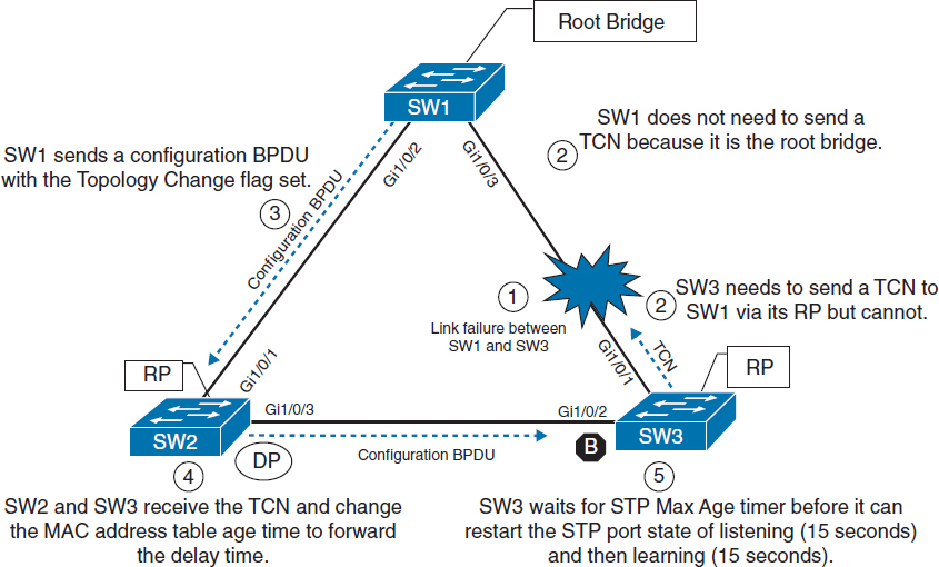
Figure 2-3 Convergence with Direct Link Failure Between SW1 and SW3
Phase 1. SW1 detects a link failure on its Gi1/0/2 interface. SW2 detects a link failure on its Gi1/0/1 interface.
Phase 2. Normally SW1 would generate a TCN flag out its root port, but it is the root bridge, so it does not. SW1 would advertise a TCN if it were not the root bridge.
SW3 removes its best BPDU received from SW1 on its Gi1/0/1 interface because it is now in a down state. At this point, SW3 would attempt to send a TCN toward the root switch to notify it of a topology change; however, its root port is down.
Phase 3. SW1 advertises a configuration BPDU with the Topology Change flag out of all its ports. This BPDU is received and relayed to all switches in the environment.
Phase 4. SW2 and SW3 receive the configuration BPDU with the Topology Change flag. These switches then reduce the MAC address age timer to the forward delay timer to flush out older MAC entries. In this phase, SW2 does not know what changed in the topology.
Phase 5. SW3 must wait until it hears from the root bridge again on the Gi1/0/2 interface (which was in the blocking state previously) to restart the listening and learning states.
The total convergence time for SW3 is 50 seconds: 20 seconds for the Max Age timer on SW3, 15 seconds for the listening state and 15 seconds for the learning state before SW3’s Gi1/0/2 can be made the RP.
Direct Link Failure Scenario 3
In the third scenario, the link between SW1 and SW2 fails. Network traffic from SW1 or SW3 toward SW2 is impacted because SW3’s Gi1/0/2 port is in a blocking state. Figure 2-4 illustrates the failure scenario and events that occur to stabilize the STP topology:
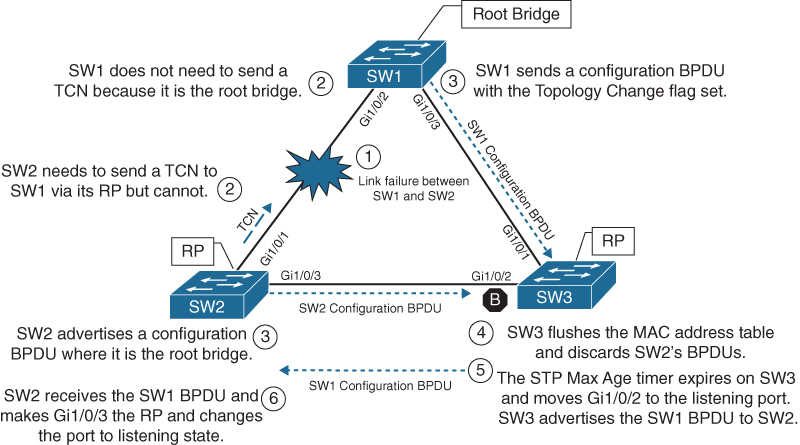
Figure 2-4 Convergence with Direct Link Failure Between SW1 and SW2
Phase 1. SW1 detects a link failure on its Gi1/0/1 interface. SW2 detects a link failure on its Gi1/0/3 interface.
Phase 2. Normally SW1 would generate a TCN flag out its root port, but it is the root bridge, so it does not. SW1 would advertise a TCN if it were not the root bridge.
SW2 removes its best BPDU received from SW1 on its Gi1/0/1 interface because it is now in a down state. At this point, SW2 would attempt to send a TCN toward the root switch to notify it of a topology change; however, its root port is down.
Phase 3. SW1 advertises a configuration BPDU with the Topology Change flag out of all its ports. This BPDU is then received and relayed to SW3. SW3 cannot relay this to SW2 as its Gi1/0/2 port is still in a blocking state.
SW2 assumes that it is now the root bridge and advertises configuration BPDUs with itself as the root bridge.
Phase 4. SW3 receives the configuration BPDU with the Topology Change flag from SW1. SW3 reduces the MAC address age timer to the forward delay timer to flush out older MAC entries. SW3 receives SW2’s inferior BPDUs and discards them as it is still receiving superior BPDUs from SW1.
Phase 5. The Max Age timer on SW3 expires, and now SW3’s Gi1/0/2 port transitions from blocking to listening state. SW3 can now forward the next configuration BPDU it receives from SW1 to SW2.
Phase 6. SW2 receives SW1’s configuration BPDU via SW3 and recognizes it as superior. It marks its Gi1/0/3 interface as the root port and transitions it to the listening state.
The total convergence time for SW2 is 52 seconds: 20 seconds for the Max Age timer on SW3, 2 seconds for the configuration BPDU from SW3, 15 seconds for the listening state on SW2, and 15 seconds for the learning state.
Indirect Failures
There are some failure scenarios where STP communication between switches is impaired or filtered while the network link remains up. This situation is known as an indirect link failure, and timers are required to detect and remediate the topology. Figure 2-5 illustrates an impediment or data corruption on the link between SW1 and SW3 along with the logic to resolve the loss of network traffic:
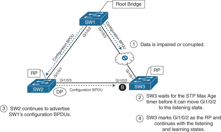
Figure 2-5 Convergence with Indirect Link Failure
Phase 1. An event occurs that impairs or corrupts data on the link. SW1 and SW3 still report a link up condition.
Phase 2. SW3 stops receiving configuration BPDUs on its RP. It keeps a cached entry for the RP on Gi1/0/1. SW1’s configuration BPDUs that are being transmitted via SW2 are discarded as SW3’s Gi1/0/2 port is in a blocking state.
Once SW3’s Max Age timer expires and flushes the RP’s cached entry, SW3 transitions Gi1/0/2 from blocking to listening state.
Phase 3. SW2 continues to advertise SW1’s configuration BPDUs toward SW3.
Phase 4. SW3 receives SW1’s configuration BPDU via SW2 on its Gi1/0/2 interface. This port is now marked as the RP and continues to transition through the listening and learning states.
The total time for reconvergence on SW3 is 50 seconds: 20 seconds for the Max Age timer on SW3, 15 seconds for the listening state on SW3, and 15 seconds for the learning state on SW3.