Building the STP Topology
This section focuses on the logic switches use to build an STP topology. Figure 2-1 shows the simple topology used here to demonstrate some important spanning tree concepts. The configurations on all the switches do not include any customizations for STP, and the focus is primarily on VLAN 1, but VLANs 10, 20, and 99 also exist in the topology. SW1 has been identified as the root bridge, and the RP, DP, and blocking ports have been identified visually to assist in the following sections.
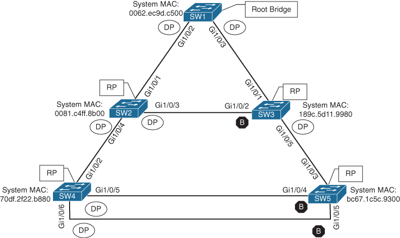
Figure 2-1 Basic STP Topology
Root Bridge Election
The first step with STP is to identify the root bridge. As a switch initializes, it assumes that it is the root bridge and uses the local bridge identifier as the root bridge identifier. It then listens to its neighbor’s configuration BPDU and does the following:
-
If the neighbor’s configuration BPDU is inferior to its own BPDU, the switch ignores that BPDU.
-
If the neighbor’s configuration BPDU is preferred to its own BPDU, the switch updates its BPDUs to include the new root bridge identifier along with a new root path cost that correlates to the total path cost to reach the new root bridge. This process continues until all switches in a topology have identified the root bridge switch.
STP deems a switch more preferable if the priority in the bridge identifier is lower than the priority of the other switch’s configuration BPDUs. If the priority is the same, then the switch prefers the BPDU with the lower system MAC.
In Figure 2-1, SW1 can be identified as the root bridge because its system MAC address (0062.ec9d.c500) is the lowest in the topology. This is further verified by using the command show spanning-tree root to display the root bridge. Example 2-1 demonstrates this command being executed on SW1. The output includes the VLAN number, root bridge identifier, root path cost, hello time, max age time, and forwarding delay. Because SW1 is the root bridge, all ports are designated ports, so the Root Port field is empty. This is one way to verify that the connected switch is the root bridge for the VLAN.
Example 2-1 Verifying the STP Root Bridge
SW1# show spanning-tree root
                                        Root    Hello Max Fwd
Vlan                   Root ID          Cost    Time  Age Dly  Root Port
---------------- -------------------- --------- ----- --- ---  ------------
VLAN0001         32769 0062.ec9d.c500         0    2   20  15
VLAN0010         32778 0062.ec9d.c500         0    2   20  15
VLAN0020         32788 0062.ec9d.c500         0    2   20  15
VLAN0099         32867 0062.ec9d.c500         0    2   20  15
In Example 2-1, notice that the root bridge priority on SW1 for VLAN 1 is 32,769 and not 32,768. The priority in the configuration BPDU packets is actually the priority plus the value of the sys-id-ext (which is the VLAN number). You can confirm this by looking at VLAN 10, which has a priority of 32,778, which is 10 higher than 32,768.
The advertised root path cost is always the value calculated on the local switch. As the BPDU is received, the local root path cost is the advertised root path cost plus the local interface port cost. The root path cost is always zero on the root bridge. Figure 2-2 illustrates the root path cost as SW1 advertises the configuration BPDUs toward SW3 and then SW3’s configuration BPDUs toward SW5.
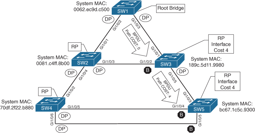
Figure 2-2 STP Path Cost Advertisements
Example 2-2 shows the output of the show spanning-tree root command run on SW2 and SW3. The Root ID field is exactly the same as for SW1, but the root path cost has changed to 4 because both switches must use the 1 Gbps link to reach SW1. Gi1/0/1 has been identified on both switches as the root port.
Example 2-2 Identifying the Root Ports
SW2# show spanning-tree root
                                        Root    Hello Max Fwd
Vlan                   Root ID          Cost    Time  Age Dly  Root Port
---------------- -------------------- --------- ----- --- ---  ------------
VLAN0001         32769 0062.ec9d.c500         4    2   20  15  Gi1/0/1
VLAN0010         32778 0062.ec9d.c500         4    2   20  15  Gi1/0/1
VLAN0020         32788 0062.ec9d.c500         4    2   20  15  Gi1/0/1
VLAN0099         32867 0062.ec9d.c500         4    2   20  15  Gi1/0/1
SW3# show spanning-tree root
Root Hello Max Fwd
Vlan Root ID Cost Time Age Dly Root Port
---------------- -------------------- --------- ----- --- --- ------------
VLAN0001 32769 0062.ec9d.c500 4 2 20 15 Gi1/0/1
VLAN0010 32778 0062.ec9d.c500 4 2 20 15 Gi1/0/1
VLAN0020 32788 0062.ec9d.c500 4 2 20 15 Gi1/0/1
VLAN0099 32867 0062.ec9d.c500 4 2 20 15 Gi1/0/1Locating Root Ports
After the switches have identified the root bridge, they must determine their root port (RP). The root bridge continues to advertise configuration BPDUs out all of its ports. The switch compares the BPDU information to identify the RP. The RP is selected using the following logic (where the next criterion is used in the event of a tie):
-
The interface associated to lowest path cost is more preferred.
-
The interface associated to the lowest system priority of the advertising switch is preferred next.
-
The interface associated to the lowest system MAC address of the advertising switch is preferred next.
-
When multiple links are associated to the same switch, the lowest port priority from the advertising switch is preferred.
-
When multiple links are associated to the same switch, the lower port number from the advertising switch is preferred.
Example 2-3 shows the output of running the command show spanning-tree root on SW4 and SW5. The Root ID field is exactly the same as on SW1, SW2, and SW3 in Examples 2-1 and 2-2. However, the root path cost has changed to 8 because both switches (SW4 and SW5) must traverse two 1 Gbps link to reach SW1. Gi1/0/2 was identified as the RP for SW4, and Gi1/0/3 was identified as the RP for SW5.
Example 2-3 Identifying the Root Ports on SW4 and SW5
SW4# show spanning-tree root
                                        Root    Hello Max Fwd
Vlan                   Root ID          Cost    Time  Age Dly  Root Port
---------------- -------------------- --------- ----- --- ---  ------------
VLAN0001         32769 0062.ec9d.c500         8    2   20  15  Gi1/0/2
VLAN0010         32778 0062.ec9d.c500         8    2   20  15  Gi1/0/2
VLAN0020         32788 0062.ec9d.c500         8    2   20  15  Gi1/0/2
VLAN0099         32867 0062.ec9d.c500         8    2   20  15  Gi1/0/2
SW5# show spanning-tree root
Root Hello Max Fwd
Vlan Root ID Cost Time Age Dly Root Port
---------------- -------------------- --------- ----- --- --- ------------
VLAN0001 32769 0062.ec9d.c500 8 2 20 15 Gi1/0/3
VLAN0010 32778 0062.ec9d.c500 8 2 20 15 Gi1/0/3
VLAN0020 32788 0062.ec9d.c500 8 2 20 15 Gi1/0/3
VLAN0099 32867 0062.ec9d.c500 8 2 20 15 Gi1/0/The root bridge can be identified for a specific VLAN through the use of the command show spanning-tree root and examination of the CDP or LLDP neighbor information to identify the host name of the RP switch. The process can be repeated until the root bridge is located.
Locating Blocked Designated Switch Ports
Now that the root bridge and RPs have been identified, all other ports are considered designated ports. However, if two non-root switches are connected to each other on their designated ports, one of those switch ports must be set to a blocking state to prevent a forwarding loop. In our sample topology, this would apply to the following links:
SW2 Gi1/0/3 ← → SW3 Gi1/0/2
SW4 Gi1/0/5 ← → SW5 Gi1/0/4
SW4 Gi1/0/6 ← → SW5 Gi1/0/5
The logic to calculate which ports should be blocked between two non-root switches is as follows:
-
The interface is a designated port and must not be considered an RP.
-
The switch with the lower path cost to the root bridge forwards packets, and the one with the higher path cost blocks. If they tie, they move on to the next step.
-
The system priority of the local switch is compared to the system priority of the remote switch. The local port is moved to a blocking state if the remote system priority is lower than that of the local switch. If they tie, they move on to the next step.
-
The system MAC address of the local switch is compared to the system MAC of the remote switch. The local designated port is moved to a blocking state if the remote system MAC address is lower than that of the local switch.
All three links (SW2 Gi1/0/3 ↔ SW3 Gi1/0/2, SW4 Gi1/0/5 ↔ SW5 Gi1/0/4, andSW4 Gi1/0/6 ↔ SW5 Gi1/0/5) would use step 4 of the process just listed to identify which port moves to a blocking state. SW3’s Gi1/0/2, SW5’s Gi1/0/4, and SW5’s Gi1/0/5 ports would all transition to a blocking state because the MAC addresses are lower for SW2 and SW4.
The command show spanning-tree [vlan vlan-id] provides useful information for locating a port’s STP state. Example 2-4 shows this command being used to show SW1’s STP information for VLAN 1. The first portion of the output displays the relevant root bridge’s information, which is followed by the local bridge’s information. The associated interface’s STP port cost, port priority, and port type are displayed as well. All of SW1’s ports are designated ports (Desg) because SW1 is the root bridge.
These port types are expected on Catalyst switches:
-
Point-to-point (P2P): This port type connects with another network device (PC or RSTP switch).
-
P2P edge: This port type specifies that portfast is enabled on this port.
Example 2-4 Viewing SW1’s STP Information
SW1# show spanning-tree vlan 1
VLAN0001
Spanning tree enabled protocol rstp
! This section displays the relevant information for the STP root bridge
Root ID    Priority    32769
            Address     0062.ec9d.c500
            This bridge is the root
            Hello Time   2 sec  Max Age 20 sec  Forward Delay 15 sec
! This section displays the relevant information for the Local STP bridge
Bridge ID  Priority    32769  (priority 32768 sys-id-ext 1)
            Address     0062.ec9d.c500
            Hello Time   2 sec  Max Age 20 sec  Forward Delay 15 sec
            Aging Time  300 sec

Interface           Role Sts Cost      Prio.Nbr Type
------------------- ---- --- --------- -------- --------------------------------
Gi1/0/2             Desg FWD 4         128.2    P2p
Gi1/0/3             Desg FWD 4         128.3    P2p
Gi1/0/14 Desg FWD 4 128.14 P2p EdgeExample 2-5 shows the STP topology for SW2 and SW3. Notice that in the first root bridge section, the output provides the total root path cost and the port on the switch that is identified as the RP.
All the ports on SW2 are in a forwarding state, but port Gi1/0/2 on SW3 is in a blocking (BLK) state. Specifically, SW3’s Gi1/0/2 port has been designated as an alternate port to reach the root in the event that the Gi1/0/1 connection fails.
The reason that SW3’s Gi1/0/2 port rather than SW2’s Gi1/0/3 port was placed into a blocking state is that SW2’s system MAC address (0081.c4ff.8b00) is lower than SW3’s system MAC address (189c.5d11.9980). This can be deduced by looking at the system MAC addresses in the output and confirmed by the topology in Figure 2-1.
Example 2-5 Verifying the Root and Blocking Ports for a VLAN
SW2# show spanning-tree vlan 1

VLAN0001
Spanning tree enabled protocol rstp
Root ID    Priority    32769
            Address     0062.ec9d.c500
             Cost        4
             Port        1 (GigabitEthernet1/0/1)
            Hello Time   2 sec  Max Age 20 sec  Forward Delay 15 sec

Bridge ID  Priority    32769  (priority 32768 sys-id-ext 1)
            Address     0081.c4ff.8b00
            Hello Time   2 sec  Max Age 20 sec  Forward Delay 15 sec
            Aging Time  300 sec

Interface           Role Sts Cost      Prio.Nbr Type
------------------- ---- --- --------- -------- --------------------------------
Gi1/0/1             Root FWD 4         128.1    P2p
Gi1/0/3             Desg FWD 4         128.3    P2p
Gi1/0/4             Desg FWD 4         128.4    P2p
SW3# show spanning-tree vlan 1
VLAN0001
Spanning tree enabled protocol rstp
! This section displays the relevant information for the STP root bridge
Root ID Priority 32769
Address 0062.ec9d.c500
Cost 4
Port 1 (GigabitEthernet1/0/1)
Hello Time 2 sec Max Age 20 sec Forward Delay 15 se
! This section displays the relevant information for the Local STP bridge
Bridge ID Priority 32769 (priority 32768 sys-id-ext 1)
Address 189c.5d11.9980
Hello Time 2 sec Max Age 20 sec Forward Delay 15 sec
Aging Time 300 sec
Interface Role Sts Cost Prio.Nbr Type
------------------- ---- --- --------- -------- --------------------------------
Gi1/0/1 Root FWD 4 128.1 P2p
Gi1/0/2 Altn BLK 4 128.2 P2p
Gi1/0/5 Desg FWD 4 128.5 P2Verification of VLANS on Trunk Links
All the interfaces that participate in a VLAN are listed in the output of the command show spanning-tree. Using this command can be a daunting task for trunk ports that carry multiple VLANs. The output includes the STP state for every VLAN on an interface for every switch interface. The command show spanning-tree interface interface-id [detail] drastically reduces the output to the STP state for only the specified interface. The optional detail keyword provides information on port cost, port priority, number of transitions, link type, and count of BPDUs sent or received for every VLAN supported on that interface. Example 2-6 demonstrates the use of both iterations of the command.
If a VLAN is missing on a trunk port, you can check the trunk port configuration for accuracy. Trunk port configuration is covered in more detail in Chapter 5, “VLAN Trunks and EtherChannel Bundles.” A common problem is that a VLAN may be missing from the allowed VLANs list for that trunk interface.
Example 2-6 Viewing VLANs Participating with STP on an Interface
SW3# show spanning-tree interface gi1/0/1

Vlan                Role Sts Cost      Prio.Nbr Type
------------------- ---- --- --------- -------- --------------------------------
VLAN0001            Root FWD 4         128.1    P2p
VLAN0010            Root FWD 4         128.1    P2p
VLAN0020            Root FWD 4         128.1    P2p
VLAN0099            Root FWD 4         128.1    P2p
SW3# show spanning-tree interface gi1/0/1 detail
! Output omitted for brevity
Port 1 (GigabitEthernet1/0/1) of VLAN0001 is root forwarding
Port path cost 4, Port priority 128, Port Identifier 128.1.
Designated root has priority 32769, address 0062.ec9d.c500
Designated bridge has priority 32769, address 0062.ec9d.c500
Designated port id is 128.3, designated path cost 0
Timers: message age 16, forward delay 0, hold 0
Number of transitions to forwarding state: 1
Link type is point-to-point by default
BPDU: sent 15, received 45908
Port 1 (GigabitEthernet1/0/1) of VLAN0010 is root forwarding
Port path cost 4, Port priority 128, Port Identifier 128.1.
Designated root has priority 32778, address 0062.ec9d.c500
Designated bridge has priority 32778, address 0062.ec9d.c500
Designated port id is 128.3, designated path cost 0
Timers: message age 15, forward delay 0, hold 0
Number of transitions to forwarding state: 1
Link type is point-to-point by default
MAC BPDU: sent 15, received 22957
..