Software CEF
Software CEF, also known as the software Forwarding Information Base, consists of the following components:
Forwarding Information Base: The FIB is built directly from the routing table and contains the next-hop IP address for each destination in the network. It keeps a mirror image of the forwarding information contained in the IP routing table. When a routing or topology change occurs in the network, the IP routing table is updated, and these changes are reflected in the FIB. CEF uses the FIB to make IP destination prefix-based switching decisions.
Adjacency table: The adjacency table, also known as the Adjacency Information Base (AIB), contains the directly connected next-hop IP addresses and their corresponding next-hop MAC addresses, as well as the egress interface’s MAC address. The adjacency table is populated with data from the ARP table or other Layer 2 protocol tables.
Figure 1-8 illustrates how the CEF table is built from the routing table. First, the FIB is built from the routing table. The 172.16.10.0/24 prefix is a static route with a next hop of 10.40.40.254, which is dependent upon the 10.40.40.0/24 prefix learned via OSPF. The adjacency pointer in the FIB for the 172.16.10.0/24 entry is exactly the same IP address OSPF uses for the 10.40.40.0/24 prefix (10.10.10.254). The adjacency table is then built using the ARP table and cross-referencing the MAC address with the MAC address table to identify the outbound interface.
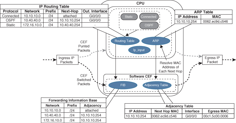
Figure 1-8 CEF Switching
Upon receipt of an IP packet, the FIB is checked for a valid entry. If an entry is missing, it is a “glean” adjacency in CEF, which means the packet should go to the CPU because CEF is unable to handle it. Valid FIB entries continue processing by looking for the appropriate adjacency entry based on that FIB record. Missing adjacency entries invoke the ARP process. Once ARP is resolved, the complete CEF entry can be created.
As part of the packet forwarding process, the packet’s headers are rewritten. The router overwrites the destination MAC address of a packet with the next-hop router’s MAC address from the adjacency table, overwrites the source MAC address with the MAC address of the outgoing Layer 3 interface, decrements the IP time-to-live (TTL) field, recomputes the IP header checksum, and finally delivers the packet to the next-hop router.
Hardware CEF
The ASICs in hardware-based routers are expensive to design, produce, and troubleshoot. ASICs allow for very high packet rates, but the trade-off is that they are limited in their functionality because they are hardwired to perform specific tasks. The routers are equipped with NPUs that are designed to overcome the inflexibility of ASICs. Unlike ASICs, NPUs are programmable, and their firmware can be changed with relative ease.
The main advantage of the distributed forwarding architectures is that the packet throughput performance is greatly improved by offloading the packet switching responsibilities to the line cards. Packet switching in distributed architecture platforms is done via distributed CEF (dCEF), which is a mechanism in which the CEF data structures are downloaded to forwarding ASICs and the CPUs of all line cards so that they can participate in packet switching; this allows for the switching to be done at the distributed level, thus increasing the packet throughput of the router.
Stateful Switchover
Routers specifically designed for high availability include hardware redundancy, such as dual power supplies and route processors (RPs). An RP is responsible for learning the network topology and building the route table (RIB). An RP failure can trigger routing protocol adjacencies to reset, resulting in packet loss and network instability. During an RP failure, it may be more desirable to hide the failure and allow the router to continue forwarding packets using the previously programmed CEF table entries rather than temporarily drop packets while waiting for the secondary RP to reestablish the routing protocol adjacencies and rebuild the forwarding table.
Stateful switchover (SSO) is a redundancy feature that allows a Cisco router with two RPs to synchronize router configuration and control plane state information. The process of mirroring information between RPs is referred to as checkpointing. SSO-enabled routers always checkpoint line card operation and Layer 2 protocol states. During a switchover, the standby RP immediately takes control and prevents basic problems such as interface link flaps. However, Layer 3 packet forwarding is disrupted without additional configuration. The RP switchover triggers a routing protocol adjacency flap that clears the route table. When the routing table is cleared, the CEF entries are purged, and traffic is no longer routed until the network topology is relearned and the forwarding table is reprogrammed. Enabling nonstop forwarding (NSF) or nonstop routing (NSR) high availability capabilities informs the router(s) to maintain the CEF entries for a short duration and continue forwarding packets through an RP failure until the control plane recovers.
SDM Templates
The capacity of MAC addresses that a switch needs compared to the number of routes that it holds depends on where it is deployed in the network. The memory used for TCAM tables is limited and statically allocated during the bootup sequence of the switch. When a section of a hardware resource is full, all processing overflow is sent to the CPU, which seriously impacts the performance of the switch.
The allocation ratios between the various TCAM tables are stored and can be modified with Switching Database Manager (SDM) templates. Multiple Cisco switches exist, and the SDM template can be configured on Catalyst 9000 switches with the global configuration command sdm prefer {vlan | advanced}. The switch must then be restarted with the reload command.
Table 1-2 shows the approximate number of resources available per template. This could vary based on the switch platform or software version in use. These numbers are typical for Layer 2 and IPv4 features. Some features, such as IPv6, use twice the entry size, which means only half as many entries can be created.
Table 1-2 Approximate Number of Feature Resources Allowed by Templates
|
Resource |
Advanced |
VLAN |
|
Number of VLANs |
4094 |
4094 |
|
Unicast MAC addresses |
32,000 |
32,000 |
|
Overflow unicast MAC addresses |
512 |
512 |
|
IGMP groups and multicast routes |
4000 |
4000 |
|
Overflow IGMP groups and multicast routes |
512 |
512 |
|
Directly connected routes |
16,000 |
16,000 |
|
Indirectly connected IP hosts |
7000 |
7000 |
|
Policy-based routing access control entries (ACEs) |
1024 |
0 |
|
QoS classification ACEs |
3000 |
3000 |
|
Security ACEs |
3000 |
3000 |
|
NetFlow ACEs |
1024 |
1024 |
|
Input Microflow policer ACEs |
256,000 |
0 |
|
Output Microflow policer ACEs |
256,000 |
0 |
|
FSPAN ACEs |
256 |
256 |
|
Control Plane Entries |
512 |
512 |
The current SDM template can viewed with the command show sdm prefer, as demonstrated in Example 1-17.
Example 1-17 Viewing the Current SDM Template
SW1# show sdm prefer
Showing SDM Template Info

This is the Advanced (high scale) template.
    Number of VLANs:                                 4094
    Unicast MAC addresses:                           32768
    Overflow Unicast MAC addresses:                  512
    IGMP and Multicast groups:                       4096
    Overflow IGMP and Multicast groups:              512
    Directly connected routes:                       16384
    Indirect routes:                                 7168
    Security Access Control Entries:                 3072
    QoS Access Control Entries:                      2560
    Policy Based Routing ACEs:                       1024
    Netflow ACEs:                                    768
    Wireless Input Microflow policer ACEs:           256
    Wireless Output Microflow policer ACEs:          256
    Flow SPAN ACEs:                                  256
    Tunnels:                                         256
    Control Plane Entries:                           512
    Input Netflow flows:                             8192
    Output Netflow flows:                            16384
    SGT/DGT and MPLS VPN entries:                    3840
    SGT/DGT and MPLS VPN Overflow entries:           512
These numbers are typical for L2 and IPv4 features.
Some features such as IPv6, use up double the entry size;
so only half as many entries can be created.