Network Device Communication
The primary function of a network is to provide connectivity between devices. There used to be a variety of network protocols that were device specific or preferred; today, almost everything is based on Transmission Control Protocol/Internet Protocol (TCP/IP). It is important to note that TCP/IP is based on the conceptual Open Systems Interconnection (OSI) model that is composed of seven layers. Each layer describes a specific function, and a layer can be modified or changed without requiring changes to the layer above or below it. The OSI model, which provides a structured approach for compatibility between vendors, is illustrated in Figure 1-1.
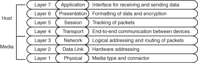
Figure 1-1 OSI Model
When you think about the flow of data, most network traffic involves communication of data between applications. The applications generate data at Layer 7, and the device/host sends data down the OSI model. As the data moves down the OSI model, it is encapsulated or modified as needed.
At Layer 3, the device/host decides whether the data needs to be sent to another application on the same device, and it would then start to move the data up the stack. Or, if the data needs to be sent to a different device, the device/host continues processing down the OSI model toward Layer 1. Layer 1 is responsible for transmitting the information on to the media (for example, cable, fiber, radio waves). On the receiving side, data starts at Layer 1, then moves to Layer 2, and so on, until it has moved completely up to Layer 7 and on to the receiving application.
This chapter reinforces concepts related to how a network device forwards traffic from either a Layer 2 or a Layer 3 perspective. The first Layer 2 network devices were bridges or switches, and Layer 3 devices were strictly routers. As technology advanced, the development of faster physical media required the ability to forward packets in hardware through ASICs. As ASIC functionality continued to develop, multilayer switches (MLSs) were invented to forward Layer 2 traffic in hardware as if they were switches; however, they can also perform other functions, such as routing packets, from a Layer 3 perspective.
Layer 2 Forwarding
The second layer of the OSI model, the data link layer, handles addressing beneath the IP protocol stack so that communication is directed between hosts. Network packets include Layer 2 addressing with unique source and destination addresses for segments. Ethernet commonly uses media access control (MAC) addresses, and other data link layer protocols such as Frame Relay use an entirely different method of Layer 2 addressing.
The focus of the Enterprise Core exam is on Ethernet and wireless technologies, both of which use MAC addresses for Layer 2 addressing. This book focuses on the MAC address for Layer 2 forwarding.
Collision Domains
The Ethernet protocol first used technologies like Thinnet (10BASE-2) and Thicknet (10BASE-5), which connected all the network devices using the same cable and T connectors. This caused problems when two devices tried to talk at the same time because the transmit cable shared the same segment with other devices, and the communication become garbled if two devices talk at the same time. Ethernet devices use Carrier Sense Multiple Access/Collision Detect (CSMA/CD) to ensure that only one device talks the same time in a collision domain. If a device detects that another device is transmitting data, it delays transmitting packets until the cable is quiet. This means devices can only transmit or receive data at one time (that is, operate at half-duplex).
As more devices are added to a cable, the less efficient the network becomes as devices wait until there is not any communication. All of the devices are in the same collision domain. Network hubs proliferate the problem because they add port density while repeating traffic, thereby increasing the size of the collision domain. Network hubs do not have any intelligence in them to direct network traffic; they simply repeat traffic out of every port.
Network switches enhance scalability and stability in a network through the creation of virtual channels. A switch maintains a table that associates a host’s Media Access Control (MAC) Ethernet addresses to the port that sourced the network traffic. Instead of flooding all traffic out of every switch port, a switch uses the local MAC address table to forward network traffic only to the destination switch port associated with where the destination MAC is attached. This drastically reduces the size of the collision domain between the devices and enables the devices to transmit and receive data at the same time (that is, operate at full duplex).
Figure 1-2 demonstrates the collision domains on a hub versus on a switch. Both of these topologies show the same three PCs, as well as the same cabling. On the left, the PCs are connected to a network hub. Communication between PC-A and PC-B is received by PC-C’s NIC, too, because all three devices are in the same collision domain. PC-C must process the frame—in the process consuming resources—and then it discards the packet after determining that the destination MAC address does not belong to it. In addition, PC-C has to wait until the PC-A/PC-B conversation finishes before it can transmit data. On the right, the PCs are connected to a network switch. Communication between PC-A and PC-B are split into two collision domains. The switch can connect the two collision domains by using information from the MAC address table.
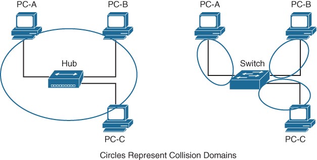
Figure 1-2 Collision Domains on a Hub Versus a Switch
When a packet contains a destination MAC address that is not in the switch’s MAC address table, the switch forwards the packet out of every switch port. This is known as unknown unicast flooding because the destination MAC address is not known.
Broadcast traffic is network traffic intended for every host on the LAN and is forwarded out of every switch port interface. This is disruptive as it diminishes the efficiencies of a network switch compared to those of a hub because it causes communication between network devices to stop due to CSMA/CD. Network broadcasts do not cross Layer 3 boundaries (that is, from one subnet to another subnet). All devices that reside in the same Layer 2 segment are considered to be in the same broadcast domain.
Figure 1-3 displays SW1’s MAC address table, which correlates the local PCs to the appropriate switch port. In the scenario on the left, PC-A is transmitting unicast traffic to PC-B. SW1 does not transmit data out of the Gi0/2 or Gi0/3 interface (which could potentially disrupt any network transmissions between those PCs). In the scenario on the right, PC-A is transmitting broadcast network traffic out all active switch ports.
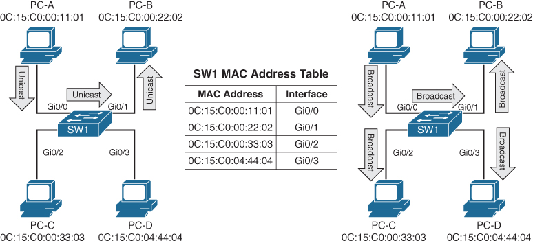
Figure 1-3 Unicast and Broadcast Traffic Patterns
Virtual LANs
Adding a router between LAN segments helps shrink broadcast domains and provides for optimal network communication. Host placement on a LAN segment varies because of network addressing. Poor host network assignment can lead to inefficient use of hardware as some switch ports could be unused.
Virtual LANs (VLANs) provide logical segmentation by creating multiple broadcast domains on the same network switch. VLANs provide higher utilization of switch ports because a port can be associated to the necessary broadcast domain, and multiple broadcast domains can reside on the same switch. Network devices in one VLAN cannot communicate with devices in a different VLAN via traditional Layer 2 or broadcast traffic.
VLANs are defined in the Institute of Electrical and Electronic Engineers (IEEE) 802.1Q standard, which states that 32 bits are added to the packet header in the following fields:
-
Tag protocol identifier (TPID): This 16-bit field is set to 0x8100 to identify the packet as an 802.1Q packet.
-
Priority code point (PCP): This 3-bit field indicates a class of service (CoS) as part of Layer 2 quality of service (QoS) between switches.
-
Drop eligible indicator (DEI): This 1-bit field indicates whether the packet can be dropped when there is bandwidth contention.
-
VLAN identifier (VLAN ID): This 12-bit field specifies the VLAN associated with a network packet.
Figure 1-4 displays the VLAN packet structure.
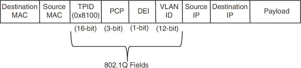
Figure 1-4 VLAN Packet Structure
The VLAN identifier has only 12 bits, which provides 4094 unique VLANs. Catalyst switches use the following logic for VLAN identifiers:
-
VLAN 0 is reserved for 802.1P traffic and cannot be modified or deleted.
-
VLAN 1 is the default VLAN and cannot be modified or deleted.
-
VLANs 2 to 1001 are in the normal VLAN range and can be added, deleted, or modified as necessary.
-
VLANS 1002 to 1005 are reserved and cannot be deleted.
-
VLANs 1006 to 4094 are in the extended VLAN range and can be added, deleted, or modified as necessary.
VLANs are created by using the global configuration command vlan vlan-id. A friendly name (32 characters) is associated with a VLAN through the VLAN submode configuration command name vlanname. The VLAN is not created until the command-line interface (CLI) has been moved back to the global configuration context or a different VLAN identifier.
Example 1-1 demonstrates the creation of VLAN 10 (PCs), VLAN 20 (Phones), and VLAN 99 (Guest) on SW1.
Example 1-1 Creating a VLAN
    SW1# configure term
Enter configuration commands, one per line. End with CNTL/Z.
SW1(config)# vlan 10
SW1(config-vlan)# name PCs
SW1(config-vlan)# vlan 20
SW1(config-vlan)# name Phones
SW1(config-vlan)# vlan 99
SW1(config-vlan)# name Guest
VLANs and their port assignment are verified with the show vlan [{brief | id vlan-id | name vlanname | summary}] command, as demonstrated in Example 1-2. Notice that the output is split into four main sections: VLAN-to-port assignments, system MTU, SPAN sessions, and private VLANs.
Example 1-2 Viewing VLAN Assignments to Port Mapping
                    SW1# show vlan
    ! Traditional and common VLANs will be listed in this section. The ports
    ! associated to these VLANs are displayed to the right.
VLAN Name                             Status    Ports
---- -------------------------------- --------- -------------------------------
1    default                          active    Gi1/0/1, Gi1/0/2, Gi1/0/3
                                                Gi1/0/4, Gi1/0/5, Gi1/0/6
                                                Gi1/0/10, Gi1/0/11, Gi1/0/17
                                                Gi1/0/18, Gi1/0/19, Gi1/0/20
                                                Gi1/0/21, Gi1/0/22, Gi1/0/23
                                                Gi1/1/1, Gi1/1/2, Te1/1/3
                                                Te1/1/4
10   PCs                              active    Gi1/0/7, Gi1/0/8, Gi1/0/9
                                                Gi1/0/12, Gi1/0/13
20   Phones                           active    Gi1/0/14
99   Guest                            active    Gi1/0/15, Gi1/0/1
1002 fddi-default                     act/unsup
1003 token-ring-default               act/unsup
1004 fddinet-default                  act/unsup
1005 trnet-default                    act/unsup
!  This section displays the system wide MTU setting for all 1Gbps and faster
!  interface

VLAN Type  SAID       MTU   Parent RingNo BridgeNo Stp  BrdgMode Trans1 Trans2
---- ----- ---------- ----- ------ ------ -------- ---- -------- ------ ------

VLAN Type  SAID       MTU   Parent RingNo BridgeNo Stp  BrdgMode Trans1 Trans2
---- ----- ---------- ----- ------ ------ -------- ---- -------- ------ ------
1    enet  100001     1500  -      -      -        -    -        0      0
10   enet  100010     1500  -      -      -        -    -        0      0
20   enet  100020     1500  -      -      -        -    -        0      0
99   enet  100099     1500  -      -      -        -    -        0      0
1002 fddi  101002     1500  -      -      -        -    -        0      0
1003 tr    101003     1500  -      -      -        -    -        0      0
1004 fdnet 101004     1500  -      -      -        ieee -        0      0
1005 trnet 101005     1500  -      -      -        ibm  -        0      0

!  If a Remote SPAN VLAN is configured, it will be displayed in this section.
!  Remote SPAN VLANs are explained in Chapter 24
Remote SPAN VLANs
------------------------------------------------------------------------------

!  If Private VLANs are configured, they will be displayed in this section.
!  Private VLANs are outside of the scope of this book, but more information
!  can be found at http://www.cisco.com
Primary Secondary Type              Ports
------- --------- ----------------- -----------------------------------------
The optional show vlan keywords provide the following benefits:
-
brief: Displays only the relevant port-to-VLAN mappings.
-
summary: Displays a count of VLANS, VLANs participating in VTP, and VLANs that are in the extended VLAN range.
-
id vlan-id: Displays all the output from the original command but filtered to only the VLAN number that is specified.
-
name vlanname: Displays all the output from the original command but filtered to only the VLAN name that is specified.
Example 1-3 shows the use of the optional keywords. Notice that the output from the optional keywords id vlan-id is the same as the output from name vlanname.
Example 1-3 Using the Optional show vlan Keywords
 show vlan brief

VLAN Name                             Status    Ports
---- -------------------------------- --------- -------------------------------
1    default                          active    Gi1/0/1, Gi1/0/2, Gi1/0/3
                                                Gi1/0/4, Gi1/0/5, Gi1/0/6
                                                Gi1/0/10, Gi1/0/11, Gi1/0/17
                                                Gi1/0/18, Gi1/0/19, Gi1/0/20
                                                Gi1/0/21, Gi1/0/22, Gi1/0/23
                                                Gi1/1/1, Gi1/1/2, Te1/1/3
                                                Te1/1/4
10   PCs                              active    Gi1/0/7, Gi1/0/8, Gi1/0/9
                                                Gi1/0/12, Gi1/0/13
20   Phones                           active    Gi1/0/14
99   Guest                            active    Gi1/0/15, Gi1/0/16
1002 fddi-default                     act/unsup
1003 token-ring-default               act/unsup
1004 fddinet-default                  act/unsup
1005 trnet-default                    act/unsup
SW1# show vlan summary
Number of existing VLANs : 8
Number of existing VTP VLANs : 8
Number of existing extended VLANS : 0SW1# show vlan id 99
VLAN Name Status Ports
---- -------------------------------- --------- -------------------------------
99 Guest active Gi1/0/15, Gi1/0/16
VLAN Type SAID MTU Parent RingNo BridgeNo Stp BrdgMode Trans1 Trans2
---- ----- ---------- ----- ------ ------ -------- ---- -------- ------ ------
99 enet 100099 1500 - - - - - 0 0
Remote SPAN VLAN
----------------
Disabled
Primary Secondary Type Ports
------- --------- ----------------- -----------------------------------------
SW1# show vlan name Guest
VLAN Name Status Ports
---- -------------------------------- --------- -------------------------------
99 Guest active Gi1/0/15, Gi1/0/16
VLAN Type SAID MTU Parent RingNo BridgeNo Stp BrdgMode Trans1 Trans2
---- ----- ---------- ----- ------ ------ -------- ---- -------- ------ ------
99 enet 100099 1500 - - - - - 0 0
Remote SPAN VLAN
----------------
Disabled
Primary Secondary Type Ports
------- --------- ----------------- -----------------------------------------Access Ports
Access ports are the fundamental building blocks of a managed switch. An access port is assigned to only one VLAN. It carries traffic from the specified VLAN to the device connected to it or from the device to other devices on the same VLAN on that switch. The 802.1Q tags are not included on packets transmitted or received on access ports.
Catalyst switches place switch ports as Layer 2 access ports for VLAN 1 by default. The port can be manually configured as an access port with the command switchport mode access. A specific VLAN is associated to the port with the command switchport access {vlan vlan-id | name vlanname}. The ability to set VLANs to an access port by name was recently added with newer code but is stored in numeric form in the configuration.
Example 1-4 demonstrates the configuration of switch ports Gi1/0/15 and Gi1/0/16 as access ports in VLAN 99 for Guests. Notice that the final configuration is stored as numbers for both ports, even though different commands are issued.
Example 1-4 Configuring an Access Port
SW1# configure terminal
Enter configuration commands, one per line. End with CNTL/Z.
SW1(config)# vlan 99
SW1(config-vlan)# name Guests
SW1(config-vlan)# interface gi1/0/15
SW1(config-if)# switchport mode access
SW1(config-if)# switchport access vlan 99
SW1(config-if)# interface gi1/0/16
SW1(config-if)# switchport mode access
SW1(config-if)# switchport access vlan name Guest

SW1# show running-config | begin interface GigabitEthernet1/0/15
interface GigabitEthernet1/0/15
    switchport access vlan 99
    switchport mode access
!
interface GigabitEthernet1/0/16
    switchport access vlan 99
    switchport mode access
Trunk Ports
Trunk ports can carry multiple VLANs. Trunk ports are typically used when multiple VLANs need connectivity between a switch and another switch, router, or firewall and use only one port. Upon receipt of the packet on the remote trunk link, the headers are examined, traffic is associated to the proper VLAN, then the 802.1Q headers are removed, and traffic is forwarded to the next port, based on MAC address for that VLAN.
Trunk ports are statically defined on Catalyst switches with the interface command switchport mode trunk. Example 1-5 displays Gi1/0/2 and Gi1/0/3 being converted to a trunk port.
Example 1-5 Configuring a Trunk Port
SW1# configure terminal
Enter configuration commands, one per line. End with CNTL/Z.
SW1(config)# interface gi1/0/2
SW1(config-if)# switchport mode trunk
SW1(config-if)# interface gi1/0/3
SW1(config-if)# switchport mode trunk
The command show interfaces trunk provides a lot of valuable information in several sections for troubleshooting connectivity between network devices:
-
The first section lists all the interfaces that are trunk ports, the status, the association to an EtherChannel, and whether a VLAN is a native VLAN. Native VLANs are explained in the next section. EtherChannel is explained in Chapter 5, “VLAN Trunks and EtherChannel Bundles.”
-
The second section of the output displays the list of VLANs that are allowed on the trunk port. Traffic can be minimized on trunk ports to restrict VLANs to specific switches, thereby restricting broadcast traffic, too. Other use cases involve a form of load balancing between network links where select VLANs are allowed on one trunk link, while a different set of VLANs are allowed on a different trunk port.
-
The third section displays the VLANs that are in a forwarding state on the switch. Ports that are in blocking state are not listed in this section.
Example 1-6 demonstrates the use of the show interfaces trunk command with an explanation of each section.
Example 1-6 Verifying Trunk Port Status
SW1# show interfaces trunk
! Section 1 displays the native VLAN associated on this port, the status and
! if the port is associated to a EtherChannel

Port        Mode             Encapsulation  Status        Native vlan
Gi1/0/2     on               802.1q         trunking      1
Gi1/0/3     on               802.1q         trunking      1

! Section 2 displays all of the VLANs that are allowed to be transmitted across
! the trunk ports

Port        Vlans allowed on trunk
Gi1/0/2     1-4094
Gi1/0/3     1-4094

Port        Vlans allowed and active in management domain
Gi1/0/2     1,10,20,99
Gi1/0/3     1,10,20,99

! Section 3 displays all of the VLANs that are allowed across the trunk and are
! in a spanning tree forwarding state

Port        Vlans in spanning tree forwarding state and not pruned
Gi1/0/2     1,10,20,99
Gi1/0/3     1,10,20,99
Native VLANs
In the 802.1Q standard, any traffic that is advertised or received on a trunk port without the 802.1Q VLAN tag is associated to the native VLAN. The default native VLAN is VLAN 1. This means that when a switch has two access ports configured as access ports and associated to VLAN 10—that is, a host attached to a trunk port with a native VLAN set to 10—the host could talk to the devices connected to the access ports.
The native VLAN should match on both trunk ports, or traffic can change VLANs unintentionally. While connectivity between hosts is feasible (assuming that they are on the different VLAN numbers), this causes confusion for most network engineers and is not a best practice.
A native VLAN is a port-specific configuration and is changed with the interface command switchport trunk native vlan vlan-id.
Allowed VLANs
As stated earlier, VLANs can be restricted from certain trunk ports as a method of traffic engineering. This can cause problems if traffic between two hosts is expected to traverse a trunk link and the VLAN is not allowed to traverse that trunk port. The interface command switchport trunk allowed vlan vlan-ids specifies the VLANs that are allowed to traverse the link. Example 1-7 displays a sample configuration for limiting the VLANs that can cross the Gi1/0/2 trunk port for VLANs 1, 10, 20, and 99.
Example 1-7 Viewing the VLANs That Are Allowed on a Trunk Link
SW1# show run interface gi1/0/1
interface GigabitEthernet1/0/1
    switchport trunk allowed vlan 1,10,20,99
    switchport mode trunk
The full command syntax switchport trunk allowed vlan {vlan-ids | all | none | add vlan-ids | remove vlan-ids | except vlan-ids} provides a lot of power in a single command. The optional keyword all allows for all VLANs, while none removes all VLANs from the trunk link. The add keyword adds additional VLANs to those already listed, and the remove keyword removes the specified VLAN from the VLANs already identified for that trunk link.
Layer 2 Diagnostic Commands
The information in the “Layer 2 Forwarding” section, earlier in this chapter, provides a brief primer on the operations of a switch. The following sections provide some common diagnostic commands that are used in the daily administration, operation, and troubleshooting of a network.
MAC Address Table
The MAC address table is responsible for identifying the switch ports and VLANs with which a device is associated. A switch builds the MAC address table by examining the source MAC address for traffic that it receives. This information is then maintained to shrink the collision domain (point-to-point communication between devices and switches) by reducing the amount of unknown unicast flooding.
The MAC address table is displayed with the command show mac address-table [address mac-address | dynamic | vlan vlan-id]. The optional keywords with this command provide the following benefits:
-
address mac-address: Displays entries that match the explicit MAC address. This command could be beneficial on switches with hundreds of ports.
-
dynamic: Displays entries that are dynamically learned and are not statically set or burned in on the switch.
-
vlan vlan-id: Displays entries that match the specified VLAN.
Example 1-8 shows the MAC address table on a Catalyst. The command in this example displays the VLAN, MAC address, type, and port that the MAC address is connected to. Notice that port Gi1/0/3 has multiple entries, which indicates that this port is connected to a switch.
Example 1-8 Viewing the MAC Address Table
SW1# show mac address-table dynamic
            Mac Address Table
-------------------------------------------

Vlan    Mac Address       Type        Ports
----    -----------       --------    -----
    1    0081.c4ff.8b01    DYNAMIC     Gi1/0/2
    1    189c.5d11.9981    DYNAMIC     Gi1/0/3
    1    189c.5d11.99c7    DYNAMIC     Gi1/0/3
    1    7070.8bcf.f828    DYNAMIC     Gi1/0/17
    1    70df.2f22.b882    DYNAMIC     Gi1/0/2
    1    70df.2f22.b883    DYNAMIC     Gi1/0/3
    1    bc67.1c5c.9304    DYNAMIC     Gi1/0/2
    1    bc67.1c5c.9347    DYNAMIC     Gi1/0/3
    99    189c.5d11.9981    DYNAMIC     Gi1/0/3
    99    7069.5ad4.c228    DYNAMIC     Gi1/0/15
    10    0087.31ba.3980    DYNAMIC     Gi1/0/9
    10    0087.31ba.3981    DYNAMIC     Gi1/0/9
    10    189c.5d11.9981    DYNAMIC     Gi1/0/3
    10    3462.8800.6921    DYNAMIC     Gi1/0/8
    10    5067.ae2f.6480    DYNAMIC     Gi1/0/7
    10    7069.5ad4.c220    DYNAMIC     Gi1/0/13
    10    e8ed.f3aa.7b98    DYNAMIC     Gi1/0/12
    20    189c.5d11.9981    DYNAMIC     Gi1/0/3
    20    7069.5ad4.c221    DYNAMIC     Gi1/0/14
Total Mac Addresses for this criterion: 19Some older technologies (such as load balancing) require a static MAC address entry in the MAC address table to prevent unknown unicast flooding. The command mac address-table static mac-address vlan vlan-id {drop | interface interface-id} adds a manual entry with the ability to associate it to a specific switch port or to drop traffic upon receipt.
The command clear mac address-table dynamic [{address mac-address | interface interface-id | vlan vlan-id}] flushes the MAC address table for the entire switch. Using the optional keywords can flush the MAC address table for a specific MAC address, switch port, or interface.
The MAC address table resides in content addressable memory (CAM). The CAM uses high-speed memory that is faster than typical computer RAM due to its search techniques. The CAM table provides a binary result for any query of 0 for true or 1 for false. The CAM is used with other functions to analyze and forward packets very quickly. Switches are built with large CAM to accommodate all the Layer 2 hosts for which they must maintain forwarding tables.
Switch Port Status
Examining the configuration for a switch port can be useful; however, some commands stored elsewhere in the configuration preempt the configuration set on the interface. The command show interfaces interface-id switchport provides all the relevant information for a switch port’s status. The command show interfaces switchport displays the same information for all ports on the switch.
Example 1-9 shows the output from the show interfaces gi1/0/5 switchport command on SW1. The key fields to examine at this time are the switch port state, operational mode, and access mode VLAN.
Example 1-9 Viewing the Switch Port Status
SW1# show interfaces gi1/0/5 switchport
Name: Gi1/0/5
! The following line indicates if the port is configured as an L2 switchport.
Switchport: Enabled
Administrative Mode: dynamic auto
! The following line indicates if the port is acting as static access port, trunk
! port, or if is down due to carrier detection (i.e. link down)
Operational Mode: down
Administrative Trunking Encapsulation: dot1q
Negotiation of Trunking: On
! The following line displays the VLAN assigned to the access port
Access Mode VLAN: 1 (default)
Trunking Native Mode VLAN: 1 (default)
Administrative Native VLAN tagging: enabled
Voice VLAN: none
Administrative private-vlan host-association: none
Administrative private-vlan mapping: none
Administrative private-vlan trunk native VLAN: none
Administrative private-vlan trunk Native VLAN tagging: enabled
Administrative private-vlan trunk encapsulation: dot1q
Administrative private-vlan trunk normal VLANs: none
Administrative private-vlan trunk associations: none
Administrative private-vlan trunk mappings: none
Operational private-vlan: none
Trunking VLANs Enabled: ALL
Pruning VLANs Enabled: 2-1001
Capture Mode Disabled
Capture VLANs Allowed: ALL

Protected: false
Unknown unicast blocked: disabled
Unknown multicast blocked: disabled
Appliance trust: none
Interface Status
The command show interface status is another useful command for viewing the status of switch ports in a very condensed and simplified manner. Example 1-10 demonstrates the use of this command and includes the following fields in the output:
-
Port: Displays the interface ID or port channel.
-
Name: Displays the configured interface description.
-
Status: Displays connected for links where a connection was detected and established to bring up the link. Displays notconnect for when a link is not detected and err-disabled when an error has been detected and the switch has disabled the ability to forward traffic out of that port.
-
VLAN: Displays the VLAN number assigned for access ports. Trunk links appear as trunk, and ports configured as Layer 3 interfaces display routed.
-
Duplex: Displays the duplex of the port. If the duplex auto-negotiated, it is prefixed by a-.
-
Speed: Displays the speed of the port. If the port speed was auto-negotiated, it is prefixed by a-.
-
Type: Displays the type of interface for the switch port. If it is a fixed RJ-45 copper port, it includes TX in the description (for example, 10/100/1000BASE-TX). Small form-factor pluggable (SFP)–based ports are listed with the SFP model if there is a driver for it in the software; otherwise, it says unknown.
Example 1-10 Viewing Overall Interface Status
SW1# show interface status

Port      Name              Status       Vlan       Duplex  Speed Type
Gi1/0/1                     notconnect   1            auto   auto 10/100/1000BaseTX
Gi1/0/2   SW-2 Gi1/0/1      connected    trunk      a-full a-1000 10/100/1000BaseTX
Gi1/0/3   SW-3 Gi1/0/1      connected    trunk      a-full a-1000 10/100/1000BaseTX
Gi1/0/4                     notconnect   1            auto   auto 10/100/1000BaseTX
Gi1/0/5                     notconnect   1            auto   auto 10/100/1000BaseTX
Gi1/0/6                     notconnect   1            auto   auto 10/100/1000BaseTX
Gi1/0/7   Cube13.C          connected    10         a-full a-1000 10/100/1000BaseTX
Gi1/0/8   Cube11.F          connected    10         a-full a-1000 10/100/1000BaseTX
Gi1/0/9   Cube10.A          connected    10         a-full  a-100 10/100/1000BaseTX
Gi1/0/10                    notconnect   1            auto   auto 10/100/1000BaseTX
Gi1/0/11                    notconnect   1            auto   auto 10/100/1000BaseTX
Gi1/0/12  Cube14.D Phone    connected    10         a-full a-1000 10/100/1000BaseTX
Gi1/0/13  R1-G0/0/0         connected    10         a-full a-1000 10/100/1000BaseTX
Gi1/0/14  R2-G0/0/1         connected    20         a-full a-1000 10/100/1000BaseTX
Gi1/0/15  R3-G0/1/0         connected    99         a-full a-1000 10/100/1000BaseTX
Gi1/0/16  R4-G0/1/1         connected    99         a-full a-1000 10/100/1000BaseTX
Gi1/0/17                    connected    1          a-full a-1000 10/100/1000BaseTX
Gi1/0/18                    notconnect   1            auto   auto 10/100/1000BaseTX
Gi1/0/19                    notconnect   1            auto   auto 10/100/1000BaseTX
Gi1/0/20                    notconnect   1            auto   auto 10/100/1000BaseTX
Gi1/0/21                    notconnect   1            auto   auto 10/100/1000BaseTX
Gi1/0/22                    notconnect   1            auto   auto 10/100/1000BaseTX
Gi1/0/23                    notconnect   routed       auto   auto 10/100/1000BaseTX
Gi1/0/24                    disabled     4011         auto   auto 10/100/1000BaseTX
Te1/1/1                     notconnect   1            full    10G SFP-10GBase-SR
Te1/1/2                     notconnect   1            auto   auto unknown