Layer 3 Forwarding
Now that we have looked at the mechanisms of a switch and how it forwards Layer 2 traffic, let’s review the process for forwarding a packet from a Layer 3 perspective. Recall that all traffic starts at Layer 7 and works its way down to Layer 1, so some of the Layer 3 forwarding logic occurs before Layer 2 forwarding. There are two main methodologies for Layer 3 forwarding:
Forwarding traffic to devices on the same subnet
Forwarding traffic to devices on a different subnet
The following sections explain these two methodologies.
Local Network Forwarding
Two devices that reside on the same subnet communicate locally. As the data is encapsulated with its IP address, the device detects that the destination is on the same network. However, the device still needs to encapsulate the Layer 2 information (that is, the source and destination MAC addresses) to the packet. It knows its own MAC address but does not initially know the destination’s MAC address.
The Address Resolution Protocol (ARP) table provides a method of mapping Layer 3 IP addresses to Layer 2 MAC addresses by storing the IP address of a host and its corresponding MAC address. The device then uses the ARP table to add the appropriate Layer 2 headers to the data packet before sending it down to Layer 2 for processing and forwarding.
For example, an IP host that needs to perform address resolution for another IP host connected by Ethernet can send an ARP request using the LAN broadcast address, and it then waits for an ARP reply from the IP host. The ARP reply includes the required Layer 2 physical MAC address information.
The ARP table contains entries for remote devices that the host has communicated with recently and that are on the same IP network segment. It does not contain entries for devices on a remote network but does contain the ARP entry for the IP address of the next hop to reach the remote network. If communication has not occurred with a host after a length of time, the entry becomes stale and is removed from the local ARP table.
If an entry does not exist in the local ARP table, the device broadcasts an ARP request to the entire Layer 2 switching segment. The ARP request strictly asks that whoever owns the IP address in the ARP request reply. All hosts in the Layer 2 segment receive the request, but only the device with the matching IP address should respond to the request.
The response is unicast and includes the MAC and IP addresses of the requestor. The device then updates its local ARP table upon receipt of the ARP reply, adds the appropriate Layer 2 headers, and sends the original data packet down to Layer 2 for processing and forwarding.
Packet Routing
Packets must be routed when two devices are on different networks. As the data is encapsulated with its IP address, a device detects that its destination is on a different network and must be routed. The device checks its local routing table to identify its next-hop IP address, which may be learned in one of several ways:
From a static route entry, it can get the destination network, subnet mask, and next-hop IP address.
A default-gateway is a simplified static default route that just asks for the local next-hop IP address for all network traffic.
Routes can be learned from routing protocols.
The source device must add the appropriate Layer 2 headers (source and destination MAC addresses), but the destination MAC address is needed for the next-hop IP address. The device looks for the next-hop IP addresses entry in the ARP table and uses the MAC address from the next-hop IP address’s entry as the destination MAC address. The next step is to send the data packet down to Layer 2 for processing and forwarding.
The next router receives the packet based on the destination MAC address, analyzes the destination IP address, locates the appropriate network entry in its routing table, identifies the outbound interface, and then finds the MAC address for the destination device (or the MAC address for the next-hop address if it needs to be routed further). The router then modifies the source MAC address to the MAC address of the router’s outbound interface and modifies the destination MAC address to the MAC address for the destination device (or next-hop router).
Figure 1-5 illustrates the concept, with PC-A sending a packet to PC-B through an Ethernet connection to R1. PC-A sends the packet to R1’s MAC address, 00:C1:5C:00:00:A1. R1 receives the packet, removes the Layer 2 information, and looks for a route to the 192.168.2.2 address. R1 identifies that connectivity to the 192.168.2.2 IP address is through Gigabit Ethernet 0/1. R1 adds the Layer 2 source address by using its Gigabit Ethernet 0/1 MAC address 00:C1:5C:00:00:B1 and the destination address 00:00:00:BB:BB:BB for PC-B.
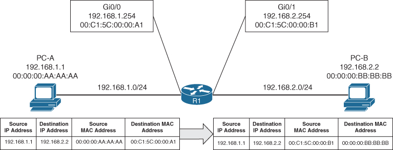
Figure 1-5 Layer 2 Addressing Rewrite
IP Address Assignment
TCP/IP has become the standard protocol for most networks. Initially it was used with IPv4 and 32-bit network addresses. The number of devices using public IP addresses has increased at an exponential rate and depleted the number of publicly available IP addresses. To deal with the increase in the number of addresses, a second standard, called IPv6, was developed in 1998; it provides 128 bits for addressing. Technologies and mechanisms have been created to allow IPv4 and IPv6 networks to communicate with each other. With either version, an IP address must be assigned to an interface for a router or multilayer switch to route packets.
IPv4 addresses are assigned with the interface configuration command ip address ip-address subnet-mask. An interface with a configured IP address and that is in an up state injects the associated network into the router’s routing table (Routing Information Base [RIB]). Connected networks or routes have an administrative distance (AD) of zero. It is not possible for any other routing protocol to preempt a connected route in the RIB.
It is possible to attach multiple IPv4 networks to the same interface by attaching a secondary IPv4 address to the same interface with the command ip address ip-address subnet-mask secondary.
IPv6 addresses are assigned with the interface configuration command ipv6 address ipv6-address/prefix-length. This command can be repeated multiple times to add multiple IPv6 addresses to the same interface.
Example 1-11 demonstrates the configuration of IP addresses on routed interfaces. A routed interface is basically any interface on a router. Notice that a second IPv4 address requires the use of the secondary keyword; the ipv6 address command can be used multiple times to configure multiple IPv6 addresses.
Example 1-11 Assigning IP Addresses to Routed Interfaces
R1# configure terminal
Enter configuration commands, one per line. End with CNTL/Z.
R1(config)# interface gi0/0/0
R1(config-if)# ip address 10.10.10.254 255.255.255.0
R1(config-if)# ip address 172.16.10.254 255.255.255.0 secondary
R1(config-if)# ipv6 address 2001:db8:10::254/64
R1(config-if)# ipv6 address 2001:DB8:10:172::254/64
R1(config-if)# interface gi0/0/1
R1(config-if)# ip address 10.20.20.254 255.255.255.0
R1(config-if)# ip address 172.16.20.254 255.255.255.0 secondary
R1(config-if)# ipv6 address 2001:db8:20::254/64
R1(config-if)# ipv6 address 2001:db8:20:172::254/64
Routed Subinterfaces
In the past, there might have been times when multiple VLANs on a switch required routing, and there were not enough physical router ports to accommodate all those VLANs. It is possible to overcome this issue by configuring the switch’s interface as a trunk port and creating logical subinterfaces on a router. A subinterface is created by appending a period and a numeric value after the period. Then the VLAN needs to be associated with the subinterface with the command encapsulation dot1q vlan-id.
Example 1-12 demonstrates the configuration of two subinterfaces on R2. The subinterface number does not have to match the VLAN ID, but if it does, it helps with operational support.
Example 1-12 Configuring Routed Subinterfaces
R2# configure terminal
Enter configuration commands, one per line. End with CNTL/Z.
R2(config-if)# int g0/0/1.10
R2(config-subif)# encapsulation dot1Q 10
R2(config-subif)# ip address 10.10.10.2 255.255.255.0
R2(config-subif)# ipv6 address 2001:db8:10::2/64
R2(config-subif)# int g0/0/1.99
R2(config-subif)# encapsulation dot1Q 99
R2(config-subif)# ip address 10.20.20.2 255.255.255.0
R2(config-subif)# ipv6 address 2001:db8:20::2/64
Switched Virtual Interfaces
With Catalyst switches it is possible to assign an IP address to a switched virtual interface (SVI), also known as a VLAN interface. An SVI is configured by defining the VLAN on the switch and then defining the VLAN interface with the command interface vlan vlan-id. The switch must have an interface associated to that VLAN in an up state for the SVI to be in an up state. If the switch is a multilayer switch, the SVIs can be used for routing packets between VLANs without the need of an external router.
Example 1-13 demonstrates the configuration of the SVI for VLANs 10 and 99.
Example 1-13 Creating a Switched Virtual Interface (SVI)
SW1# configure terminal
Enter configuration commands, one per line. End with CNTL/Z.
SW1(config)# interface Vlan 10
SW1(config-if)# ip address 10.10.10.1 255.255.255.0
SW1(config-if)# ipv6 address 2001:db8:10::1/64
SW1(config-if)# no shutdown
SW1(config-if)# interface vlan 99
SW1(config-if)# ip address 10.99.99.1 255.255.255.0
SW1(config-if)# ipv6 address 2001:db8:99::1/64
SW1(config-if)# no shutdown
Routed Switch Ports
Some network designs include a point-to-point link between switches for routing. For example, when a switch needs to connect to a router, some network engineers would build out a transit VLAN (for example, VLAN 2001), associate the port connecting to the router to VLAN 2001, and then build an SVI for VLAN 2001. There is always the potential that VLAN 2001 could exist elsewhere in the Layer 2 realm or that spanning tree could impact the topology.
Instead, the multilayer switch port can be converted from a Layer 2 switch port to a routed switch port with the interface configuration command no switchport. Then the IP address can be assigned to it. Example 1-14 demonstrates port Gi1/0/14 being converted from a Layer 2 switch port to a routed switch port and then having an IP address assigned to it.
Example 1-14 Configuring a Routed Switch Port
SW1# configure terminal
Enter configuration commands, one per line. End with CNTL/Z.
SW1(config)# int gi1/0/14
SW1(config-if)# no switchport
SW1(config-if)# ip address 10.20.20.1 255.255.255.0
SW1(config-if)# ipv6 address 2001:db8:20::1/64
SW1(config-if)# no shutdown
Verification of IP Addresses
IPv4 addresses can be viewed with the command show ip interface [brief | interface-id | vlan vlan-id]. This command’s output contains a lot of useful information, such as MTU, DHCP relay, ACLs, and the primary IP address. The optional brief keyword displays the output in a condensed format. However, on devices with large port counts, using the CLI parser and adding an additional | exclude field (for example, unassigned) yields a streamlined view of interfaces that are configured with IP addresses.
Example 1-15 shows the show ip interface brief command used with and without the CLI parser. Notice the drastic reduction in unnecessary data that is presented.
Example 1-15 Viewing Device IPv4 Addresses
SW1# show ip interface brief
Interface              IP-Address      OK? Method Status                Protocol
Vlan1                  unassigned      YES manual up                    up
Vlan10                 10.10.10.1      YES manual up                    up
Vlan99                 10.99.99.1      YES manual up                    up
GigabitEthernet0/0     unassigned      YES unset  down                  down
GigabitEthernet1/0/1   unassigned      YES unset  down                  down
GigabitEthernet1/0/2   unassigned      YES unset  up                    up
GigabitEthernet1/0/3   unassigned      YES unset  up                    up
GigabitEthernet1/0/4   unassigned      YES unset  down                  down
GigabitEthernet1/0/5   unassigned      YES unset  down                  down
GigabitEthernet1/0/6   unassigned      YES unset  down                  down
GigabitEthernet1/0/7   unassigned      YES unset  up                    up
GigabitEthernet1/0/8   unassigned      YES unset  up                    up
GigabitEthernet1/0/9   unassigned      YES unset  up                    up
GigabitEthernet1/0/10  unassigned      YES unset  down                  down
GigabitEthernet1/0/11  unassigned      YES unset  down                  down
GigabitEthernet1/0/12  unassigned      YES unset  down                  down
GigabitEthernet1/0/13  unassigned      YES unset  up                    up
GigabitEthernet1/0/14  10.20.20.1      YES manual up                    up
GigabitEthernet1/0/15  unassigned      YES unset  up                    up
GigabitEthernet1/0/16  unassigned      YES unset  up                    up
GigabitEthernet1/0/17  unassigned      YES unset  down                  down
SW1# show ip interface brief | exclude unassigned
Interface              IP-Address      OK? Method Status                Protocol
Vlan10                 10.10.10.1      YES manual up                    up
Vlan99                 10.99.99.1      YES manual up                    up
GigabitEthernet1/0/14  10.20.20.1      YES manual up                    up
GigabitEthernet1/0/23  192.168.1.1     YES manual down                  down
The same information can be viewed for IPv6 addresses with the command show ipv6 interface [brief | interface-id | vlan vlan-id]. Just as with IPv4 addresses, a CLI parser can be used to reduce the information to what is relevant, as demonstrated in Example 1-16.
Example 1-16 Viewing Device IPv6 Addresses
SW1# show ipv6 interface brief
! Output omitted for brevity
Vlan1                  [up/up]
    FE80::262:ECFF:FE9D:C547
    2001:1::1
Vlan10                 [up/up]
    FE80::262:ECFF:FE9D:C546
    2001:DB8:10::1
Vlan99                 [up/up]
    FE80::262:ECFF:FE9D:C55D
    2001:DB8:99::1
GigabitEthernet0/0     [down/down]
    unassigned
GigabitEthernet1/0/1   [down/down]
    unassigned
GigabitEthernet1/0/2   [up/up]
    unassigned
GigabitEthernet1/0/3   [up/up]
    unassigned
GigabitEthernet1/0/4   [down/down]
    unassigned
GigabitEthernet1/0/5   [down/down]
    Unassigned
SW1# show ipv6 interface brief | exclude unassigned|GigabitEthernet
Vlan1 [up/up]
FE80::262:ECFF:FE9D:C547
2001:1::1
Vlan10 [up/up]
FE80::262:ECFF:FE9D:C546
2001:DB8:10::1
Vlan99 [up/up]
FE80::262:ECFF:FE9D:C55D
2001:DB8:99::1